


News
Application of Fault Indicators in Remote Overhead Lines of Rural Power Grid
Date:2023-07-07
1. Problems Existing in Traditional Line Fault Location Methods in Remote Rural Areas
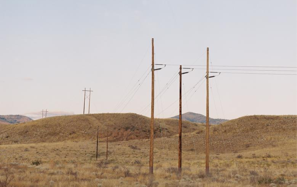
Distribution networks in remote rural areas are generally distributed in villages and mountainous areas with long lines and are easily damaged by external forces. To accurately find out the type of fault and locate it when a fault occurs on the line, it is necessary to consider the grounding method of the neutral point of the line, because the grounding method of the neutral point affects the characteristic appearance after the fault occurs. In the medium and high voltage power transmission and distribution network below 35 kV, most of them adopt the neutral point ungrounded or grounded through the arc suppression coil, that is, the small current grounding method. When a single-phase ground fault occurs, it is difficult to locate the fault point in remote rural areas due to long lines, small loads, weak fault current, and unstable fault characteristics. Traditional fault location methods such as traveling wave ranging method, impedance method and signal injection method have not been widely used due to high cost, large amount of calculation and complicated application.
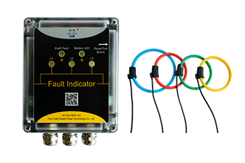
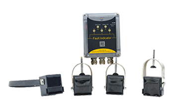
2. Application of fault indicators
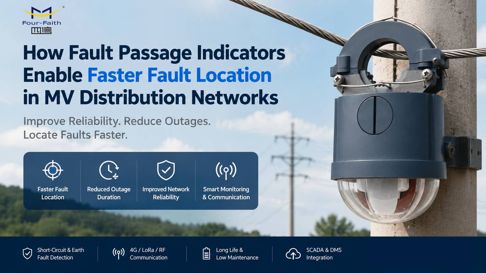
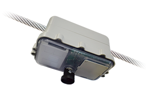
The fault indicator is an intelligent detection device installed on the power line to indicate the fault current path. It can intelligently judge, give early warning, display faults in real time and automatically reset. The setting mode of the early fault indicator is fixed, and only one specific current value is available for selection. Due to the influence of current fluctuations, inrush currents, high-order harmonics, distributed capacitance and electromagnetic interference (EMI), the general action accuracy is not high. In recent years, due to the rapid development of electronics, sensing and communication technologies, new fault indicators have been widely used. The new fault indicator is generally based on digital electronic components, and its action logic and setting value can be set and adjusted according to the length of the line, load level, protection mode and other factors, which further enhances the practicability of the fault indicator.
3. Short Circuit Fault Detection
For the detection of short-circuit faults, one is the current mutation detection method, that is, when the line current suddenly increases from the operating current to the fault current, a positive mutation occurs, and the change is greater than a set value, and then in a very short If the current and voltage drop to 0 within the time, it is determined that the line current is the fault current. The advantage of this method is that it is only related to the short-circuit current component during a fault, and has nothing to do with the magnitude of the line current. It is a fault detection device that can adapt to changes in load current. Its disadvantage is that the sensitivity is poor when the short-circuit current is small.
The other method is similar to the principle of substation outlet relay protection. Standard quick-break and over-current criteria are used. If the parameters are set properly, all short-circuit actions can be guaranteed (two-phase short-circuit, three-phase short-circuit, two-phase-to-ground short-circuit, resistance Or single-phase grounding short circuit of direct grounding system) higher fault judgment accuracy. Its advantage is that it has a wide range of applications, especially for remote lines in rural power grids, which are different from general indicators that require a large sudden change of current. The disadvantage is that the user is required to have a better understanding of the line conditions, and the parameter settings must be reasonable.
4. Single Phase-to-Earth Fault Detection
The judgment of the single-phase ground fault in the small current grounding system is more complicated, and the commonly used methods mainly include the harmonic method and the first half-wave method. The 5th harmonic method, for the 5th harmonic component, because of its small value, it is more susceptible to external interference; the first half-wave method, if the fault occurs near the voltage zero point, the transient component of the current is small, it is the first detection method. The half-wave dead zone is likely to cause misjudgment of polarity. Since the single-phase fault indicator can only detect the current and induced electric field of the current phase, in the existing single-phase ground fault detection methods, any method that needs to detect the zero-sequence component and compare the measured quantities of each line to make a judgment is not suitable. Suitable for use on overhead lines.
The current grounding system at 35 kV is a small current grounding system. There is no definite mathematical model in the theoretical circle, only a physical model, and all parameters in the physical model are variable, so it is impossible to accurately determine the grounding system based on inherent hardware or software criteria. Determine the ground fault. Some manufacturers use transient ground current and transient steady-state ground voltage change characteristics for comprehensive comparison, and if necessary, manually participate in the analysis method of decision-making and judgment. This is a relatively effective method for judging single-phase ground fault points in small current grounding systems. When selecting the model, the product must have a very high data sampling frequency, which can continuously capture the discharge current of the line capacitance at the moment of grounding (milliseconds to sub-milliseconds).
Another factor that needs to be considered when selecting the type of fault indicator is that it is required to have the function of preventing inrush current misoperation during no-load closing and non-faulty line misoperation during reclosing.
At present, all Four-Faith fault indicators use the most optimized technical research and judgment logic, combined with the actual situation of distribution network lines in remote areas of rural power grids, and design them to better serve electric power utilities.
RECOMMEND NEWS


RECOMMEND PRODUCTS
-
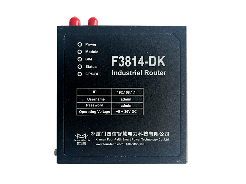
Industrial Wireless Router F3X14-DK
-
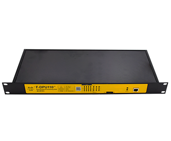
Intelligent Protocol Gateway F-DPU110-RK
-
Protocol Converter Gateway F-DPU100-RK
-
Industrial IP Modem F2X14-DK
-
Underground Fault indicator DYO-FF-FIS
-
Underground Fault indicator DYO-FF-FI
-
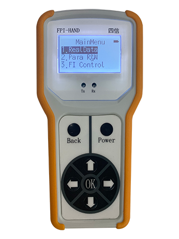
Hand-held Tool FPI-Hand
-
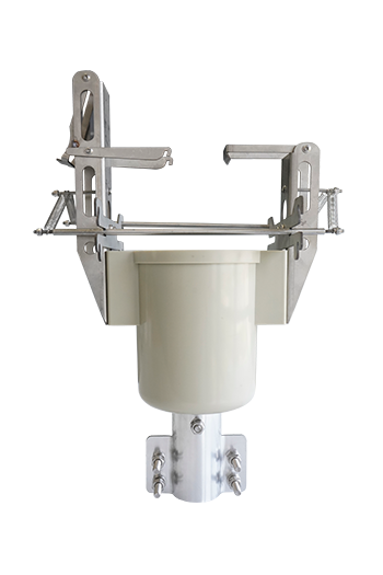
Hot Stick Tool
-
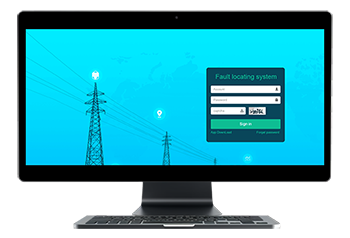
Four-Faith Fault Location System
-
Communication Unit JYL-FF-HX
-

Communication Unit JYZ-FF-HD
-
LED Fault indicator JYZ-HW
-
Flag Fault indicator JYZ-FF
top
- Products
- Distribution Automation
- Outdoor Apparatus
- Fault Circuit Indicator
- Industrial Wireless Communication
- Software
- Solutions
- Utility Solutions
- Infrastructure Solutions
- Services
- Documents & Software
- Support
- Business Case
- Video
- about us
- Company
- Contact us
- Subscribe
- Career

Mobile viewing


© Copyright 2026 by www.fourfaithpower.com. All Rights Reserved. 闽ICP备08106834号-8

