News
Advantages of Power Line Fault Indicators
Date:2022-12-01
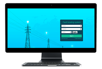
The emergence of power line fault indicators is due to the fact that there are many branches of the distribution network, the operation mode is changeable and the structure is complex. It is difficult to locate the fault by using traveling wave ranging or impedance calculation, which leads to the management and maintenance of the line and the repair of faults. The workload is greatly increased, and the power failure indicator allows the patrol personnel to quickly find the fault line according to the alarm display of the indicator for processing and recovery, which improves the reliability of power supply.

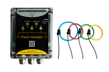
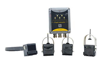
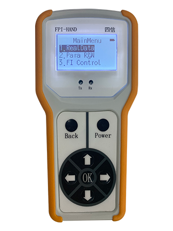
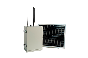
The power line fault indicator is composed of a sensor and a display. The sensor is responsible for detecting the current passing through the cable, and the display is responsible for judging the current information transmitted by the sensor and making fault indication actions.
After the power line fault indicator is installed on the line, when the system fails, due to the fault current in the line from the fault point to the feed point, all the power line fault indicators on the line from the fault point to the feed point will act. The indicator light will flash. Starting from the feed point, search along the line where the power line fault indicator light is flashing. The last flashing point is the fault point. Promoting the use of cable fault indicators helps to find the fault point in a short time, and is an effective way to improve the operation level of the distribution network and the efficiency of accident handling.
1. According to the function of use:
1.1 Short-circuit type;
1.2 Grounding type;
1.3 Grounding and short circuit two-in-one type.
2. According to the signal source:
2.1 Line fault detection system with signal source;
2.2 No signal source line fault indicator.
3. According to the installation location:
3.1 Overhead line type;
3.2 Cable line type;
3.3 bus bar type; 3.4 panel type.
4. According to the display mode:
4.1 Flop display type;
4.2 Photoelectric display type.
5. According to the line power supply mode:
5.1 Single power supply type;
5.2 Dual power supply type.
6. The following is a brief introduction to three different power line fault indicators according to the classification method of the installation site.
6.1 Overhead line fault indicator
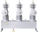
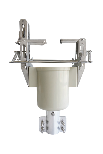
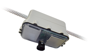
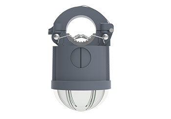
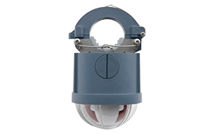
The sensor and the display (indicating) part are integrated into one unit, and the indicator is mechanically fixed on a certain phase line of the overhead line (including bare wires and insulated wires). It should have a communication function, configure a communication module, and return information such as faults, line current, and low battery power to the data receiving device connected to it. It should be able to load and unload with electricity, and no false alarm should be given during the loading and unloading process.
6.2 Cable type ground fault indicator
The sensor and display (indicating) part are integrated in one unit, fixed on a certain phase cable line (busbar) by mechanical means, usually installed on the indicator on the distribution equipment such as cable branch box, ring network cabinet, switch cabinet, etc. . In addition to the above requirements, a zero-sequence ground fault indicator also needs to be configured.
6.3 Panel type power line fault indicator
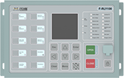
It is mainly used in supporting equipment such as cable branch boxes and ring network cabinets. It is an indicator composed of a sensor and a display unit, usually the display unit is embedded on the operation panel of the ring network cabinet and switch cabinet. The detection principle is basically the same as that of the cable-type short-circuit and cable-type ground fault indicators. The difference is that the detector detects a fault and transmits it to the host through an optical fiber cable, and sends an alarm signal through the host. The sensor and the display unit communicate by means of optical fiber or wireless, and the primary and secondary should be reliably insulated.

