


News
Application Principle and Function Introduction of New Power Line Fault Indicator
Date:2022-12-08
The application principle of the new power line fault indicator in the era of Four-Faith Smart Power Internet of Things.
The intelligent fault indicator with wireless communication function, when the line fails, in addition to flipping and flashing display, at the same time, the signal is sent to the collection unit in a short distance through the wireless transmitting unit. The communication terminal of the converging unit is usually installed on the overhead line tower. After receiving the RF signal, the fault signal is transmitted through the 2G/3G/4G module. Now there are many who start to use LoRa and NB-IoT module communication.
The power line fault indicator does not work frequently, and the data transmission distance of the acquisition device is relatively long, so LoRa and NB-IoT are more suitable than other communication methods. NB-IoT has a better future development prospect in China, although the cost of NB-IoT modules High, the cost should be greatly reduced after large-scale application in the future. For places with poor 4G signal coverage such as remote areas, the signal of LoRa will be more stable than that of NB-IoT, and both are low power consumption. LoRa is relatively less power-efficient than NB-IoT.

1. What is a new power line fault indicator
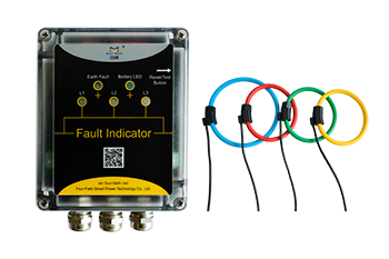
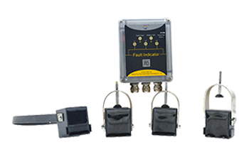
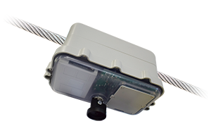
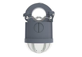
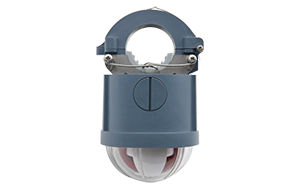
Different types of power line fault indicators. These indicators are installed on the power line. According to the structure of the clamping line, there are overhead type, cable type, panel type and other fault indicators. The current passing through the line can be detected by the sensor, and faults such as short circuit and grounding can be monitored. , when a fault condition occurs, the flop will display red during the day, and the LED will flash to display at night. The main performance parameters of the power line fault indicator include voltage level, load current, wire cross section, number of actions, weight, wind resistance, battery life, etc. Subharmonics, current fluctuations, and the influence of cable distributed capacitance bypass.
2. How to judge the fault node when the power line fault indicator is working
With the fault indicator, how to find the fault point? As shown in the figure below: After a short circuit or ground fault occurs in the power line, all fault indicators on the line from the substation to the fault point will operate, and a red flash will be given during the day. Card display, flashing instructions at night, and the fault indicator behind the fault point will not act, so that the fault area can be found, the fault branch can be found, and the fault point can be confirmed.
The power fault indicator has the functions of line load monitoring, short-circuit fault, and ground fault indication, which can help line-finding personnel quickly find fault points, shorten power outage time, and improve power supply reliability.
3. The fault indicator developed by Four-Faith mainly has the following functions:
3.1 Short circuit alarm indication function
The short-circuit sensor detects the current of the line during operation. When the short-circuit fault occurs on the line and the current reaches or exceeds the set value of the short-circuit current, the short-circuit sensor sends out an alarm signal, which is transmitted to the host through the optical cable. After the host receives this signal, it generates a corresponding alarm indication. Signal.
3.2 Grounding alarm indication function
The grounding sensor detects the zero-sequence current of the line during work. When the grounding fault occurs in the line, when the grounding current reaches or exceeds the set value of the grounding current, the grounding sensor sends out an alarm signal, which is transmitted to the host through the optical cable. After the host receives this signal, it generates Corresponding alarm indication signal.
3.3 Automatic reset function
When the indicator sends out an alarm signal, if there is no manual reset, the indicator can be automatically reset after a certain time.
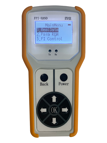
3.4 Manual reset function
When the indicator generates an alarm, the alarm can be canceled by pressing the "reset/test" button on the panel of the indicator host for 2 seconds.
3.5 Automated functions
After the indicator generates the corresponding alarm indication signal, the alarm signal can be output to remote transmission. The indicator can also receive a remote reset signal to perform a remote reset operation on the indicator.
RECOMMEND NEWS


RECOMMEND PRODUCTS


top
- Products
- Distribution Automation
- Outdoor Apparatus
- Fault Circuit Indicator
- Industrial Wireless Communication
- Software
- Solutions
- Utility Solutions
- Infrastructure Solutions
- Services
- Documents & Software
- Support
- Business Case
- Video
- about us
- Company
- Contact us
- Subscribe
- Career

Mobile viewing


© Copyright 2026 by www.fourfaithpower.com. All Rights Reserved. 闽ICP备08106834号-8

