


News
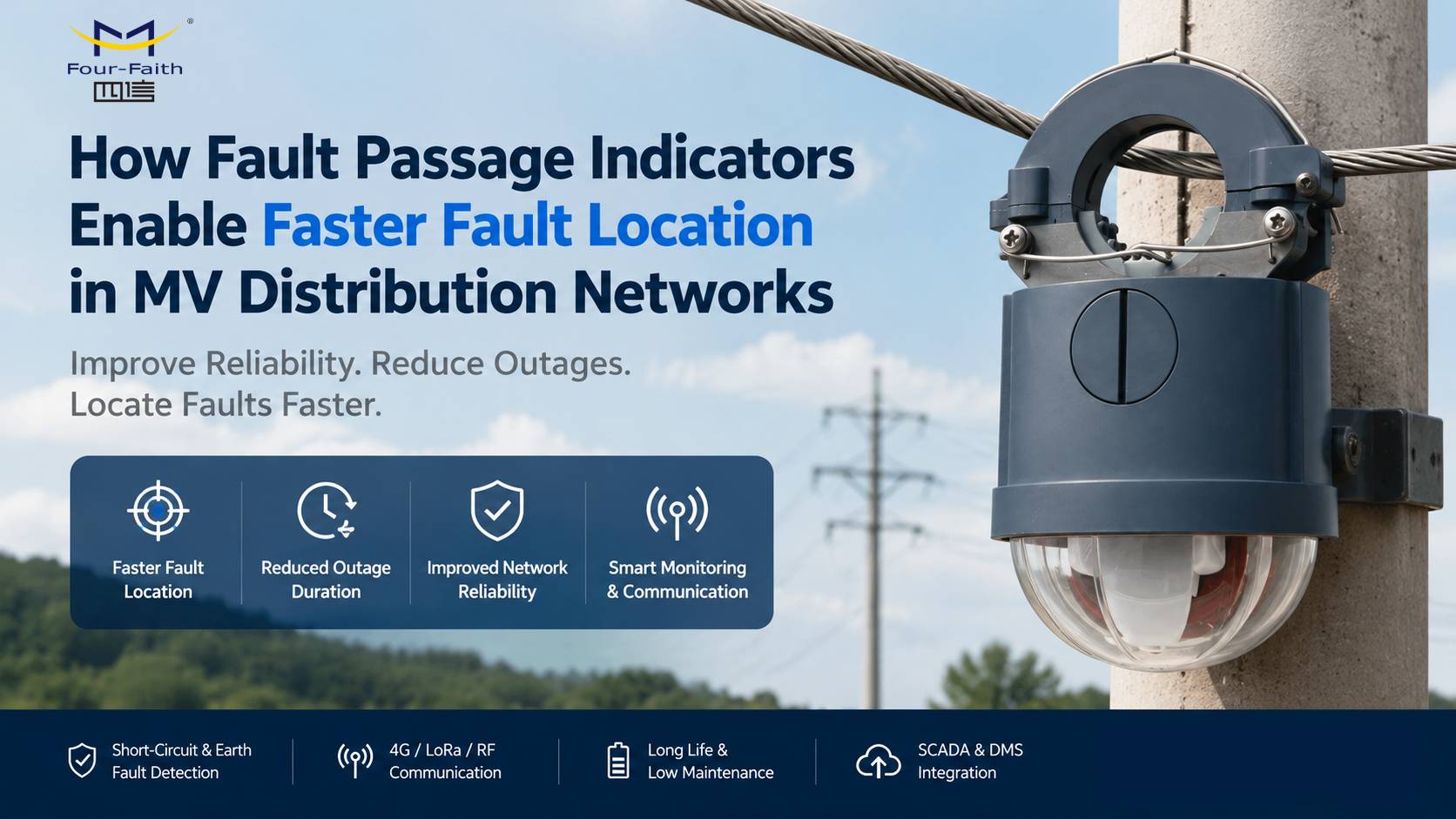
How Does an Underground Fault Indicator Work?
Date:2026-01-19
As power distribution networks continue to expand and modernize, underground cable systems are increasingly preferred for their safety, aesthetics, and resistance to weather-related damage. However, locating faults in underground cables can be time-consuming and costly. This is where Underground Fault Indicators (UFIs) play a crucial role.
What Is an Underground Fault Indicator?
An Underground Fault Indicator is a monitoring device installed in underground power distribution systems to detect and identify cable faults. It helps utility operators quickly determine whether a fault has occurred and pinpoint the faulted section, significantly reducing outage time and maintenance costs.
These devices are commonly used in medium-voltage (MV) and high-voltage (HV) underground networks, including urban distribution grids, industrial facilities, and critical infrastructure.
Types of Faults in Underground Cables
Underground fault indicators are designed to detect several common fault types, including:
Short-circuit faults (phase-to-phase or phase-to-ground)
Earth (ground) faults
Overcurrent faults
Transient faults caused by insulation breakdown or moisture ingress
Understanding these fault types is essential to appreciating how fault indicators work.
How Does an Underground Fault Indicator Work?
Underground fault indicators operate by continuously monitoring electrical parameters in the cable system. The working process can be broken down into several key steps:
1. Current and Voltage Sensing
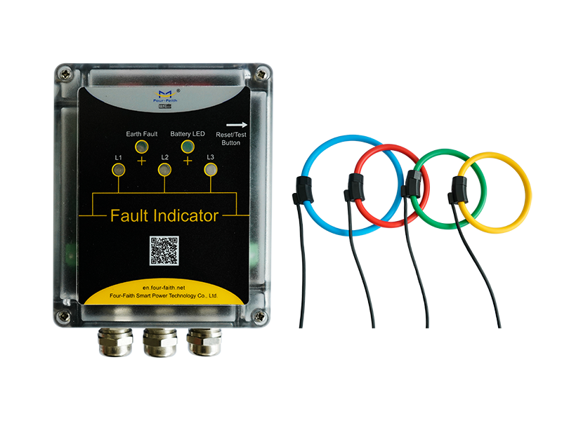
The indicator uses built-in current sensors, such as Rogowski coils or current transformers, to measure the flow of current in the cable. Some advanced models also include voltage sensors to detect changes in system voltage.
When a fault occurs, the fault current rises sharply or the voltage drops abnormally—these deviations trigger the indicator.
2. Fault Detection Logic
The device is programmed with predefined threshold values for current magnitude, direction, and duration. When these thresholds are exceeded, the indicator’s internal logic confirms that a fault condition exists rather than a normal load fluctuation.
Modern fault indicators can distinguish between:
Load current and fault current
Permanent faults and temporary faults
Directional and non-directional faults
3. Fault Direction Identification (Optional)
Directional underground fault indicators analyze current direction and phase angle to determine whether the fault is upstream or downstream of the device. This feature is especially valuable in ring main units (RMUs) and looped distribution networks.
4. Indication and Communication
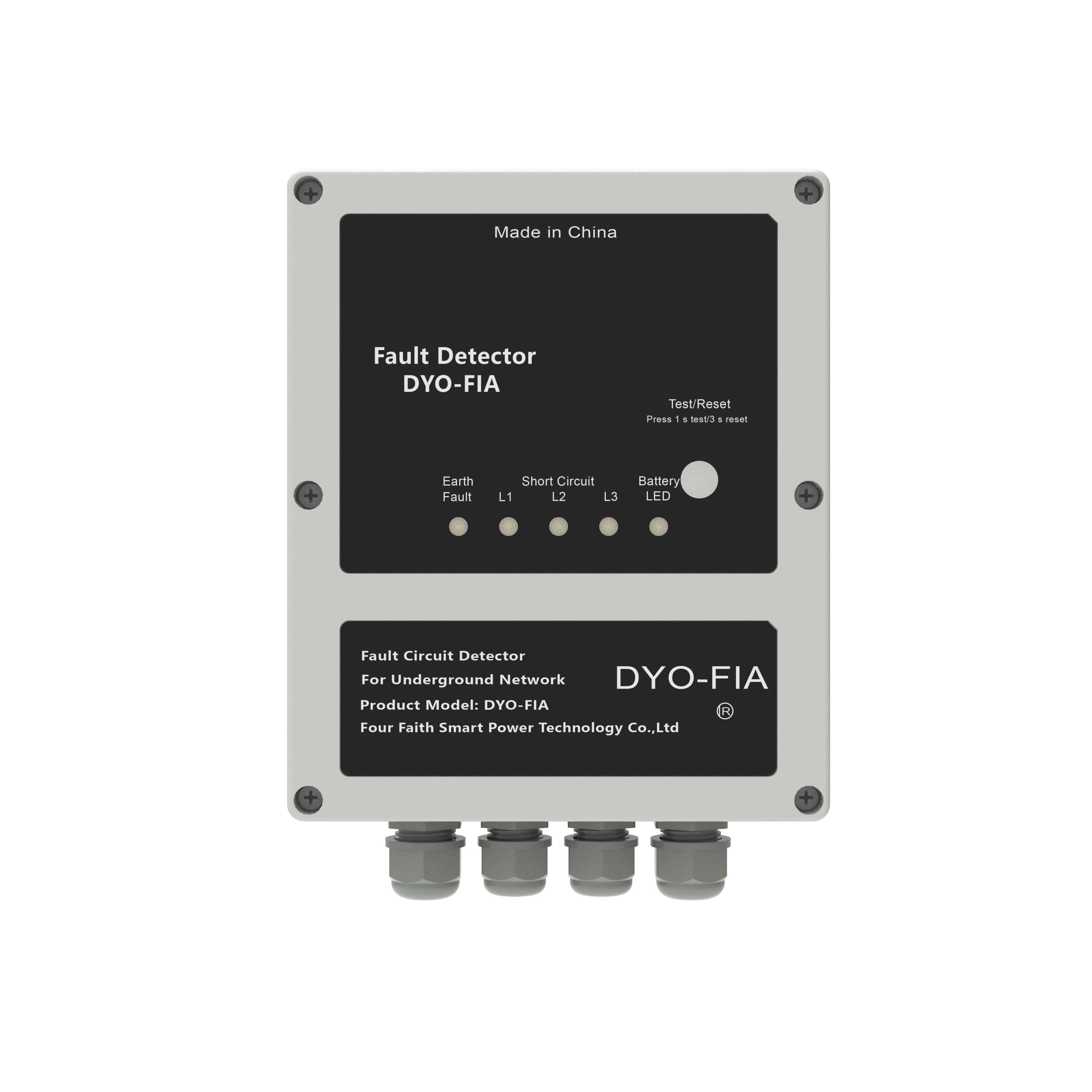
Once a fault is detected, the indicator provides a clear alert through:
Visual indicators (LEDs or mechanical flags)
Remote communication via SCADA, GSM, NB-IoT, or LoRa networks
This allows maintenance teams to locate the faulted cable section without extensive manual inspection.
5. Reset and Recovery
After the fault is cleared, the indicator can be:
Automatically reset once normal current is restored
Manually reset by field technicians
Remotely reset via communication systems (in smart grid applications)
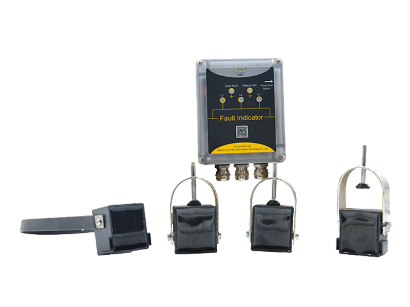
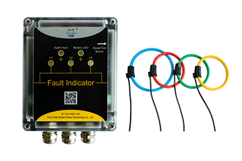
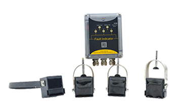
Key Components of an Underground Fault Indicator
An underground fault indicator typically consists of:
Current and/or voltage sensors
Microprocessor-based control unit
Power supply (battery or self-powered from line current)
Visual display or indicator
Communication module (optional)
Benefits of Using Underground Fault Indicators
Deploying underground fault indicators offers several advantages:
Faster fault location and reduced outage duration
Lower operational and maintenance costs
Improved grid reliability and customer satisfaction
Enhanced safety for maintenance personnel
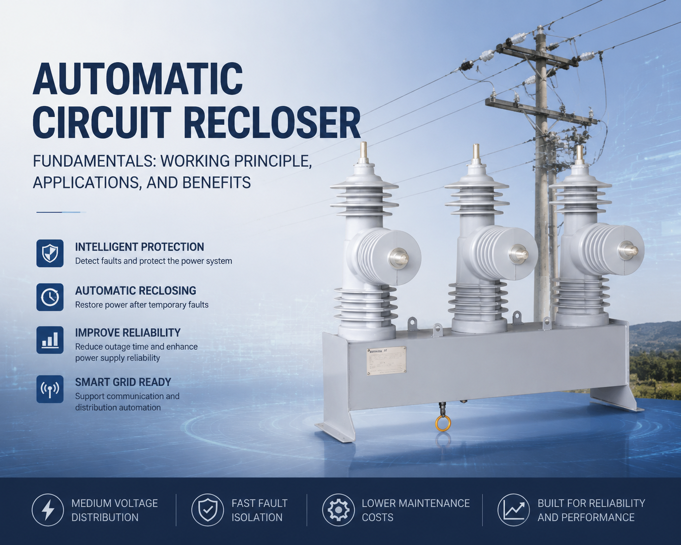
Better integration with smart grid systems
Applications of Underground Fault Indicators
Underground fault indicators are widely used in:
Urban power distribution networks
Industrial plants and campuses
Renewable energy integration systems
Airports, hospitals, and data centers
Smart grid and distribution automation projects
Conclusion
An underground fault indicator works by continuously monitoring current and voltage conditions, detecting abnormal fault signatures, and providing immediate local or remote alerts. By enabling faster fault identification and isolation, these devices are essential tools for modern underground power distribution systems.
As utilities move toward smarter and more reliable grids, underground fault indicators will continue to play a vital role in minimizing downtime and improving network efficiency.
RECOMMEND NEWS

RECOMMEND PRODUCTS

top
- Products
- Distribution Automation
- Outdoor Apparatus
- Fault Circuit Indicator
- Industrial Wireless Communication
- Software
- Solutions
- Utility Solutions
- Infrastructure Solutions
- Services
- Documents & Software
- Support
- Business Case
- Video
- about us
- Company
- Contact us
- Subscribe
- Career

Mobile viewing


© Copyright 2026 by www.fourfaithpower.com. All Rights Reserved. 闽ICP备08106834号-8

